


Views: 0 Author: Site Editor Publish Time: 2026-08-22 Origin: Site


Machine speed and tonnage mean nothing if the punch fails at the point of impact. High-volume CNC punching relies entirely on the tooling executing the strike. Subpar punches and dies lead to premature wear. They cause edge burrs and force unacceptable machine downtime. Plant managers and tooling engineers face a saturated market of OEM and aftermarket providers. You must balance upfront tooling expenses with long-term grind life, setup efficiency, and scrap reduction.
Trumpf configurations operate differently than Amada or Thick Turret systems. These setups are specifically engineered for applications demanding ultra-precision. They excel in environments requiring rapid offline setup. We need a strict technical evaluation framework for selecting the right components. This guide explores alignment systems, metallurgical properties, and application-specific configurations. You will learn how to maximize Overall Equipment Effectiveness (OEE) on your shop floor.
Offline Alignment is a Multiplier: The primary advantage of Trumpf style systems is the pre-aligned cartridge design; selecting tooling that optimizes this feature almost entirely eliminates machine idle time during changeovers.
Grind Life Dictates Overall Expenses: Evaluating the usable grind life—specifically seeking out 2-4-1 tooling designs that offer twice the grind life—is more critical to overall expenses than the initial purchase price.
Application-Specific Geometry Matters: Standard punching requires different metallurgical properties and coatings compared to high-friction operations like tapping, forming, or slitting.
OEM vs. Aftermarket Requires Scrutiny: High-tier aftermarket tooling can match or exceed OEM specifications, provided strict tolerances, ease of assembly, and cartridge compatibility are verified.
The Trumpf style system relies on a unique mechanical foundation. It uses an integrated linear tool magazine. This magazine moves along a robust rail system located at the front or side of the machine. The design allows rapid access to all available punches and dies without rotating a massive turret. The linear rail delivers the exact tool to the punching head quickly and precisely. This reduces mechanical wear on the machine frame. It also speeds up the overall punching cycle, especially during complex nests requiring multiple tool changes.
The punching head itself features a single, highly rigid ram. Because the ram only strikes one station at a time, the machine maintains perfect concentricity. The hydraulic ram rotates 360 degrees, allowing any tool to be indexed at any angle. This eliminates the need for specialized auto-index stations found in other machine brands. Every tool in the linear magazine becomes an auto-index tool automatically.
Tool cartridges form the heart of this architecture. These cartridges accept pre-aligned punches, strippers, and dies. Operators assemble and align these components offline on a dedicated workbench. You complete the setup while the machine continues running another job. Rapid, error-free tool changes become the standard operating procedure.
The operator simply slides the pre-set cartridge into the linear magazine. The machine clamps it automatically when called by the CNC program. This entirely eliminates manual alignment inside the machine envelope. The cartridge system protects the tooling from dust and debris while sitting in the magazine. It also standardizes the loading process, reducing operator fatigue and minimizing the risk of dropping expensive components into the machine bed.
Thick Turret and Murata setups use massive rotating disks. You must load tools directly into the turret stations. This often requires stopping the machine for extended periods to swap out dies and align punches. The linear rail cartridge system operates differently by separating tool preparation from machine operation. Utilizing trumpf style tooling is the ideal choice for ultra-precision manufacturing. It holds tight tolerances because the ram strikes a single, rigid tool holder.
Turret systems can suffer from station wear over time. The bores in the turret expand, causing the punch to drift off-center. The linear design maintains consistent punch-to-die concentricity because the clamping mechanism secures the cartridge fresh every time. You do not have to worry about a worn turret bore ruining your clearance accuracy.
Selected tooling must seamlessly integrate with existing shop infrastructure. You need absolute compatibility with tool presetters and alignment fixtures. Poorly machined aftermarket parts can cause micro-misalignments during assembly. These tiny errors multiply during high-speed operation. They lead to rapid edge degradation and poor part quality.
Verify that new punches seat perfectly in your existing cartridges without forcing them.
Ensure the alignment ring locks without excessive play or wobble.
Check that the stripper plate floats smoothly on its springs without binding against the punch body.
Confirm that the die shoe clamps securely into the die base without shifting under lateral pressure.
Tight manufacturing tolerances prevent punch-to-die misalignment. The gap between the punch and die must remain perfectly uniform all the way around the perimeter. This clearance accuracy directly impacts part edge quality. It reduces unwanted nibbling marks on the finished sheet and eliminates the need for secondary deburring operations.
If the tooling shifts even slightly, the clearance becomes uneven. One side cuts cleanly while the other side tears the metal. High-quality manufacturing ensures the punch stays perfectly centered. You must demand tooling providers supply inspection reports verifying their dimensional accuracy. A deviation of just a few thousandths of an inch will destroy a die when punching thin aluminum.
Recommended Die Clearance Percentages
Material Type | Material Thickness Range | Recommended Clearance (% of thickness) |
|---|---|---|
Aluminum (5052, 6061) | 0.030" - 0.125" | 10% - 15% |
Mild Steel (A36, CRS) | 0.030" - 0.125" | 15% - 20% |
Mild Steel (A36, CRS) | 0.130" - 0.250" | 20% - 25% |
Stainless Steel (304, 316) | 0.030" - 0.125" | 20% - 25% |
Tooling must withstand severe off-center loading. Partial hits place massive lateral stress on the punch body. When you nibble a large radius or cut a sheet edge, the punch only engages the material on one side. Heavy-duty slitting operations generate similar sideways forces. The structural rigidity of the tool prevents deflection.
Deflection causes the punch to shave the die edge. This ruins both components instantly and sends shrapnel across the machine bed. Look for robust tool bodies machined from hardened steel blanks. They resist bending under maximum machine tonnage. The mounting rings and alignment collars must also feature hardened steel construction to absorb these lateral shocks without deforming. Applying a rooftop or whisper shear angle to the punch face also reduces the total tonnage required, further protecting the tool body from stress fractures.
Standard high-speed tool steels handle basic mild steel punching well. They offer decent edge retention for everyday tasks and are easy to sharpen. However, premium powder metallurgical steels provide a massive upgrade for demanding environments. They deliver superior impact resistance and wear characteristics.
Powdered metal tools resist micro-chipping on the cutting edge. The uniform grain structure of the steel prevents catastrophic cracking under heavy loads. This makes them perfect for punching hard materials like stainless steel or thick plate. The initial investment is higher, but the performance justifies the expense. You will change tools less often and spend less time at the grinding wheel.
Tool Steel Grade Comparison
Steel Grade | Primary Application | Toughness | Wear Resistance |
|---|---|---|---|
M2 High-Speed Steel | General purpose mild steel, aluminum | Moderate | Moderate |
D2 Tool Steel | Thick mild steel, low-volume stainless | Low | High |
PM-M4 Powder Metallurgy | High-volume stainless, abrasive materials | High | Very High |
Specialized coatings drastically improve tool performance. Titanium Carbonitride (TiCN) reduces friction during the punching stroke. Optima or proprietary nitride coatings prevent material galling. Galling occurs when aluminum or galvanized steel melts slightly and welds to the punch tip under extreme pressure.
This buildup ruins hole dimensions and strips the sheet aggressively on the upstroke. Proper surface treatments keep the punch tip clean. They allow the tool to slide through sticky materials effortlessly. Coatings also increase the surface hardness of the punch, protecting the cutting edge from abrasive materials like fiberglass or laminated metals.
Tooling designs engineered for maximum sharpening longevity provide massive value to high-volume shops. Some systems offer a 2-4-1 design. These configurations yield twice the usable grind life of standard tools. You remove more material during sharpening before discarding the punch. This is achieved through adjustable punch heads or specialized shimming systems inside the cartridge.
Evaluate how easily these extended-life tools assemble. Faster tool room processing keeps your machines fed. Reduced tooling inventory frees up valuable capital. Simple assembly mechanisms prevent operator frustration and setup errors. If an extended-life tool takes thirty minutes to adjust and assemble, the labor costs negate the material savings.
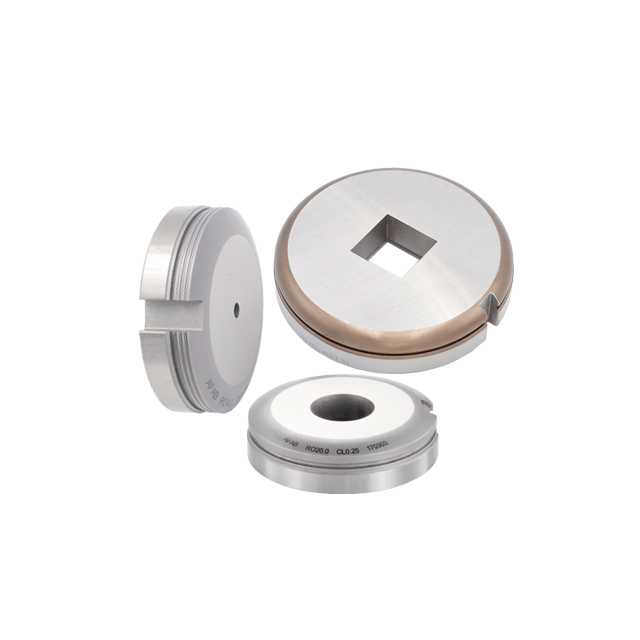
Everyday punching operations require reliable, highly efficient solutions. The Trumpf Standard Die fits this role perfectly. It handles standard hole punching in mild steel and aluminum flawlessly. You use this die for the vast majority of your nested parts. It offers excellent durability without unnecessary mechanical complexity.
Standard dies are easy to sharpen and quick to load into the die base. They form the backbone of any high-volume punching department. Because they are standardized, you can keep a large inventory of common sizes on hand. This ensures you never stop production waiting for a basic round or square die to arrive from the manufacturer.
Selecting the correct die clearance prevents slug pulling. It also eliminates excessive burrs on the bottom of the sheet. You must base clearance on material type, thickness, and shear strength. Mild steel typically requires a clearance of 15% to 20% of material thickness. Stainless steel demands slightly more clearance, often 20% to 25%, due to higher shear strength.
Aluminum requires tighter clearances, around 10% to 15%, to cleanly fracture the soft metal. Incorrect clearance causes the slug to jam in the die or pull back up onto the sheet. A pulled slug will be crushed by the next punch stroke, destroying the tool and ruining the workpiece. Always consult clearance charts provided by your tooling manufacturer. You can also specify dies with slug-free geometry, which features a slight hourglass shape inside the die matrix to trap the waste material securely.
In-machine tapping eliminates secondary manual operations. It requires highly specialized tooling configurations. You must match pitch specifications exactly to the required thread. Lubrication channels within the tool deliver oil directly to the tap during the rotation cycle. Setup rigidity is non-negotiable for clean threads.
The CNC programming integration must synchronize the ram stroke and rotation perfectly. Any lag in the machine axis will snap the tap instantly. You must also monitor the tap for wear closely. A dull tap requires more torque to cut the thread, which can overload the rotating ram mechanism. Use form taps for softer materials to eliminate chip evacuation issues inside the machine.
Forming operations require precise stroke control. Louvers, extrusions, and countersinks push metal rather than cutting it. You must select forming tools with exact stripper configurations. The stripper holds the sheet flat while the form takes shape. If the stripper pressure is too low, the sheet distorts and bows.
Precise length adjustments on the tool body dictate the form height. Operators must dial in these measurements carefully during offline setup. You also need to program the machine to slow down during the forming stroke. Hitting a forming tool at full punching speed will shatter the die matrix and tear the sheet metal.
Comparing OEM and high-end aftermarket tooling requires looking at long-term expenses. OEM tools guarantee compatibility but often carry a premium price tag. Premium aftermarket alternatives can match or exceed these performance metrics. You must evaluate the cost per hit rather than the initial invoice.
A cheaper tool that dulls twice as fast costs you more in downtime and sharpening labor. High-tier aftermarket brands invest heavily in metallurgy to compete with OEMs. They often provide superior powder metal options that outlast standard OEM offerings. Always run a physical trial to compare hit counts before committing to a massive tooling changeover.
Supply chain reliability dictates your vendor selection. A broken punch stops production immediately. You need a vendor with local inventory of replacement components. Waiting weeks for a replacement tool from overseas is unacceptable in a just-in-time manufacturing environment.
Evaluate the delivery speed of standard shapes and sizes. Fast shipping keeps your machines running and your customers happy. Reliable availability is often more valuable than a slight discount on price. Ask prospective vendors about their stock levels for your most commonly used punch sizes and die clearances.
Sometimes standard shapes cannot produce a specific part feature. You need custom shapes or specialized cluster tools. Aftermarket manufacturers often engineer these custom solutions faster than standard OEM channels. They have dedicated engineering teams for rapid prototyping.
A custom cluster tool can punch multiple holes in a single hit. This drastically reduces the total sheet processing time and minimizes sheet distortion. Evaluate the vendor's ability to turn around custom drawings quickly. A responsive engineering team proves that the vendor treats you as a partner, not just an account number.
Tooling Source Comparison
Evaluation Criteria | OEM Tooling | Premium Aftermarket Tooling |
|---|---|---|
Initial Investment | Generally higher upfront cost | Highly competitive, often lower upfront |
Compatibility Guarantee | 100% guaranteed out of the box | Requires initial tolerance verification |
Custom Shape Lead Time | Standardized, can be slower | Often optimized for rapid turnaround |
Metallurgical Options | Standardized catalog offerings | Wide variety of specialized powder metals |
Running dull tooling exponentially increases punching force. The machine must push harder to break through the material. This excess force leads to accelerated machine wear. It strains the hydraulic ram, the seals, and the main frame. Eventually, it causes catastrophic tool failure.
The punch can shatter inside the die. This ruins the cartridge and potentially damages the linear rail. Over-dulling also creates massive burrs that ruin part quality. Your deburring department will become a massive bottleneck, slowing down the entire factory flow. The heat generated by a dull punch also alters the metallurgy of the sheet edge, making downstream bending operations unpredictable.
Establish a proactive sharpening schedule based on hit counts. Do not wait for burrs to appear on the parts. Utilize automated tool tracking software integrated into your CNC control. Grind a small amount of material off frequently. This keeps the edge pristine and maximizes total tool life.
Train operators to inspect punch edges during every shift change. Use proper coolant during the grinding process to prevent heat checking. Heat checking creates micro-cracks in the tool steel that lead to premature failure. Always demagnetize the tools after grinding to prevent metal dust from clinging to the cutting edge.
Incorrect offline alignment destroys productivity. If the punch and die are not perfectly aligned, they collide. This damages the expensive cartridges instantly. It results in scrapped sheets and rejected parts. Compromised tool life is the best-case scenario of poor alignment.
The worst-case scenario involves severe damage to the punching head. Rushed setups in the tool room directly cause these failures. When operators guess the alignment angle instead of using proper fixtures, the machine pays the price. A misaligned shaped tool will also cut the hole at the wrong angle, ruining the part geometry.
Implement standardized training protocols for all tool room personnel. Leverage visual assembly tutorials provided by tooling manufacturers. Mandate the use of calibrated alignment fixtures for every setup. Never rely on visual alignment alone.
Enforce strict torque specifications during assembly. Use torque wrenches to secure retaining bolts. This prevents components from vibrating loose during high-speed punching cycles. Clean the cartridge bores thoroughly before inserting new tools. A single metal chip trapped between the tool and the cartridge wall will throw off the entire alignment.
Standardized Offline Assembly Protocol
Clean all cartridge bores and tool surfaces with a degreasing solvent.
Inspect the punch collar and alignment ring for burrs or wear marks.
Insert the punch into the alignment fixture and lock the angle securely.
Apply the manufacturer-specified torque to all retaining bolts.
Verify stripper plate spring tension manually before loading the cartridge into the machine rail.
Audit your current punch and die inventory to identify components with excessive wear, galling, or micro-cracking.
Calculate your average hit count between sharpening cycles to establish a baseline for future tooling trials.
Request physical test samples from premium aftermarket vendors to compare edge retention against your existing setup.
Implement a standardized offline cartridge assembly checklist for all tool room personnel to eliminate alignment errors.
A: The main advantage is the linear rail and pre-aligned cartridge system. Operators assemble and align tools offline while the machine runs. This eliminates manual alignment inside the machine, drastically reducing downtime during job changeovers and maintaining ultra-precise punch-to-die concentricity.
A: You should sharpen dies proactively based on hit counts and material type, rather than waiting for burrs to form. Frequent, light grinding removes less material overall and keeps the cutting edge pristine, which significantly extends the total lifespan of the die.
A: Extended-life tooling features a specialized punch body design that allows for deeper sharpening. By adjusting the tool length within the cartridge after grinding, operators can safely remove twice as much material over the tool's lifespan compared to standard configurations.
A: Offline alignment allows operators to prepare the next job's tools while the current job is still running. This parallel processing means the machine never sits idle waiting for tool setup, directly increasing the availability and performance metrics of your OEE calculation.
A: For stainless steel, Titanium Carbonitride (TiCN) or specialized proprietary nitride coatings are highly recommended. These surface treatments reduce friction, resist extreme heat, and prevent the hard stainless material from galling and welding to the punch tip during operation.
A: Prevent slug pulling by selecting the exact die clearance for your specific material type and thickness. Additionally, you can use dies with specialized slug-free geometry, which creates a slight restriction that traps the slug in the die matrix after the stroke.


